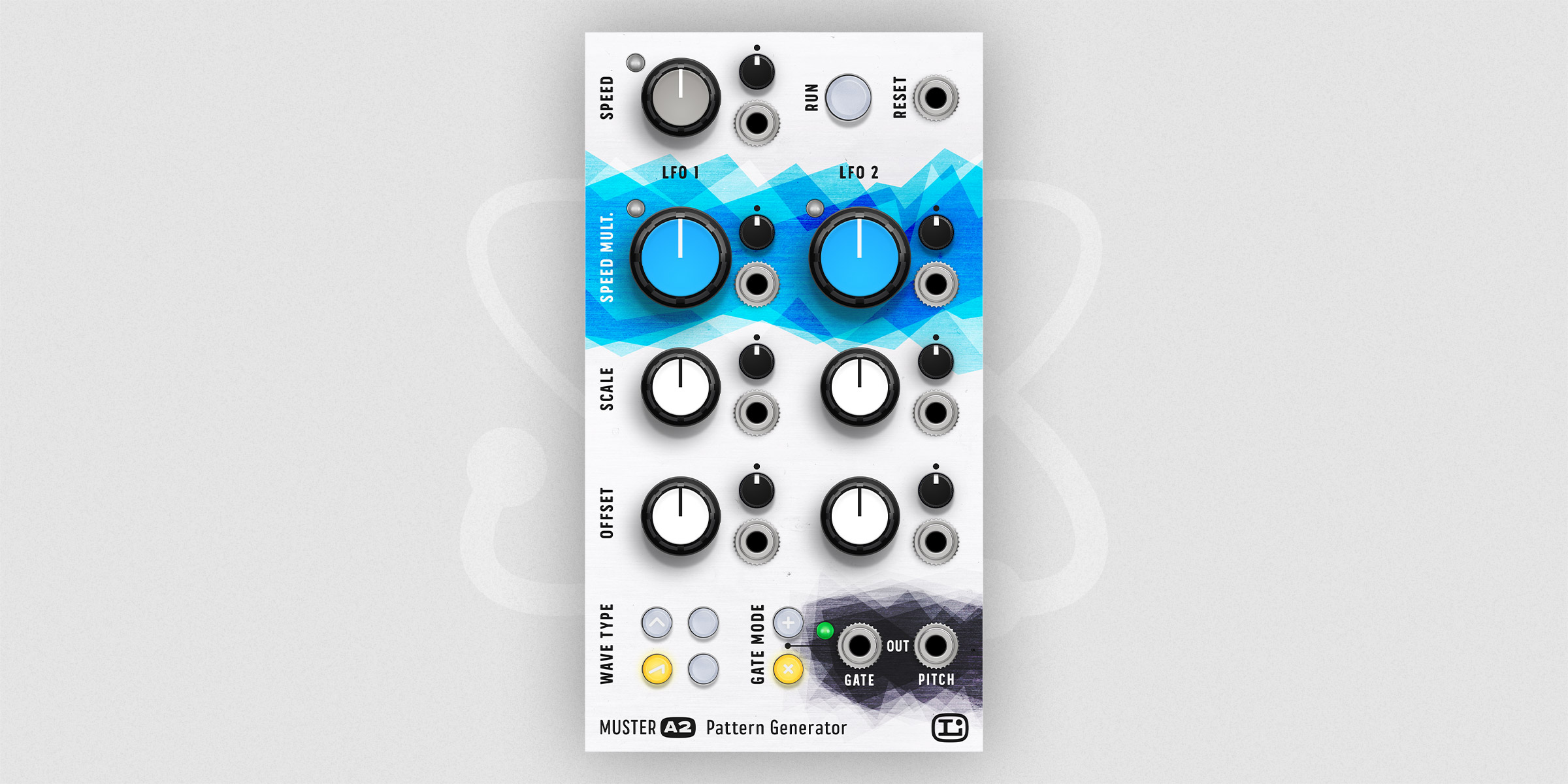
Muster A2
Muster A2 is an advanced pattern generator.
Muster A2 is part of the paid Muster package, and it is the only module capable of using different LFO signal types (sin/sqr/tri/saw). One can leverage up to 2 LFOs to create the gate and pitch signal pattern.
The gate signal is generated by LFO 1 and LFO 2. The selected speeds of the LFOs create a repeating gate signal (0 Volt is Gate off, +10 Volt is Gate on).
The pitch signal is based on LFO 3 and its speed settings. The pitch signal is limited to ±10 Volt.
The signal of each LFO can be additionally modified and modulated using the Scale and Offset parameters.
Notes
- Additional Muster A2 signals can be accessed using the Muster Ax expander.


| Parameter | Description |
|---|---|
| GATE (port) | Output port: Gate signal based on LFO 1 and LFO 2. The signal can be modified using the corresponding Scale and Offset knobs. |
| PITCH (port) | Output port: Pitch signal based on LFO 2. The signal can be modified using the corresponding Scale and Offset knobs. The resulting signal is calculated using the following formula output = (input * Scale) + Offset. |
| LFO-L - Frequency | Frequency of the Lead LFO. All other LFO frequencies are based on this leading frequency. |
| LFO-L - Frequency (port) | Input port: the modulation signal. It can be any signal in the range of ±10.0 volts. |
| LFO-L - Frequency (mod) | The modulation amount can be adjusted in the range of ±100.0%. When set to any negative value, the modulation signal will be inverted. |
| Run | Start/Stop to output the GATE and PITCH signal. |
| Reset (port) | Input port: Reset the phase of LFO 1/2 to 0. The Lead LFO will continue to operate. |
| LFO-1/2 - Multiplier | The multiplier is the ratio between the Lead LFO frequency and the LFO 1/2 frequency. The multiplier can be entered in the range of 1-10. Where 1 is the same frequency as the Lead LFO frequency and 10 is ten times the frequency. |
| LFO-1/2 - Multiplier (port) | Input port: the modulation signal |
| LFO-1/2 - Multiplier (mod) | The modulation amount can be adjusted in the range of ±100.0%. When set to any negative value, the modulation signal will be inverted. |
| LFO-1/2 - Scale | Scales the LFO 1/2 signal. Scale can be entered in the range of ±1. Where -1 is the inverted signal, 0 is no signal, and +1 is the original pitch signal. |
| LFO-1/2 - Scale (port) | Input port: the modulation signal |
| LFO-1/2 - Scale (mod) | The modulation amount can be adjusted in the range of ±100.0%. When set to any negative value, the modulation signal will be inverted. |
| LFO-1/2 - Offset | Offset is a DC offset of the LFO 1/2 signal. It can be entered in the range of ±1, which equals ±2.5 volts. |
| LFO-1/2 - Offset (port) | Input port: the modulation signal |
| LFO-1/2 - Offset (mod) | The modulation amount can be adjusted in the range of ±100.0%. When set to any negative value, the modulation signal will be inverted. |
| Wave Type - Sin | The LFOs will generate a sinus waveform. |
| Wave Type - Tri | The LFOs will generate a triangle waveform. |
| Wave Type - Saw | The LFOs will generate a sawtooth waveform. |
| Wave Type - Sqr | The LFOs will generate a square waveform. |
| Gate Mode - Plus | “Plus” combination mode of the LFO 1 and LFO 2 signal. The Gate Modes can be combined in the following ways Plus(off) and Mult(off): LFO 1 Plus(on) and Mult(off): LFO 1 + LFO 2 Plus(off) and Mult(on): LFO 1 * LFO 2 Plus(on) and Mult(on): (LFO 1 + LFO 2) * (LFO 1 * LFO 2) |
| Gate Mode - Mult | “Multiplication” combination mode of the LFO 1 and LFO 2 signal. |
Copyright
Oxidlab holds the copyright for the product concept, algorithm, and support material (e.g., manual).
Visual Concept and Artwork: Chris Corrado
