Entferner L – Low-Pass Filter
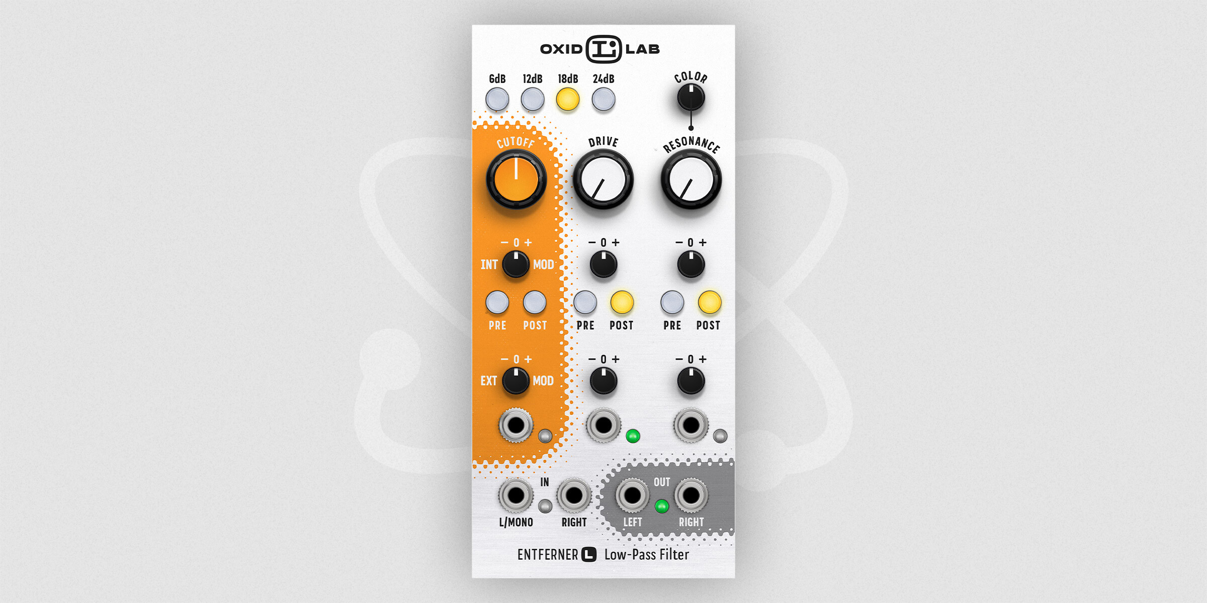
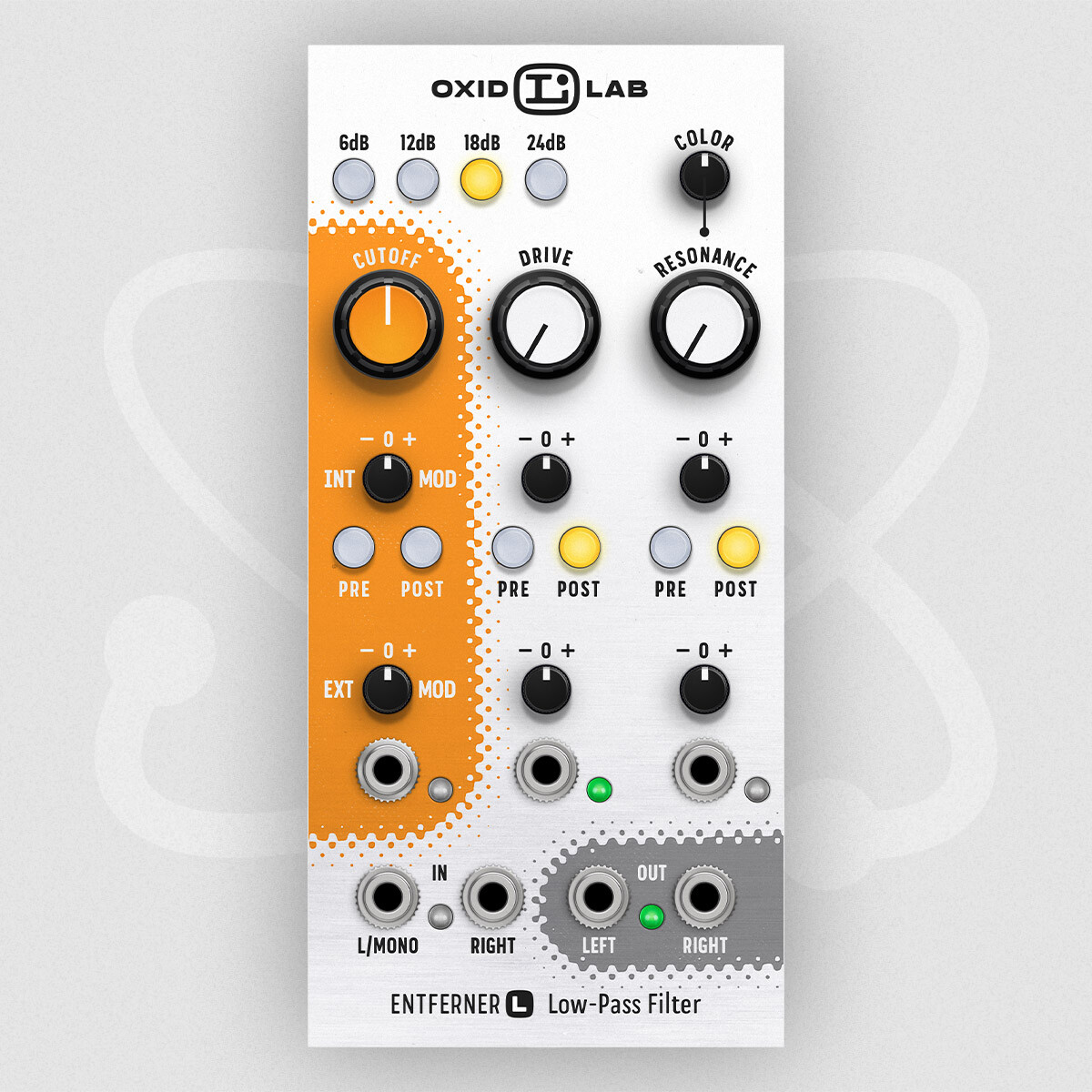
Entferner L is a stereo, resonant, and self-oscillating 6/12/18/24dB low-pass filter.
Entferner filters, in general, are based on a cascade of very versatile 6dB filters. In the case of the Entferner L filter, up to four of the 6dB filters are used and can be modulated either using the internal signal or any external CV.
Since the filter is using internal saturation, the sound is highly dependent on the input voltages. Red LED lights beside the ports indicate any voltage overdrive. If the LED is blinking from time to time, the filter is operating in its sweet spot. If the LED is continuously red, the filter will still work but might result in a harsh sound or unwanted behavior.
In case you are looking for an even more aggressive sound also check out the Entferner LE 12dB low-pass filter.
Notes
- The self-oscillation is not pitch-perfect over the whole filter range.
- Some aliasing may occur in case of extreme cutoff, resonance and/or drive values.
- Audio rate modulation is possible, but the filter behaves differently to what you might expect.


| Parameter | Description |
|---|---|
| Cutoff | The cutoff frequency controls the spectral content of the sound. A cutoff can be entered in the range of 10Hz-18kHz. |
| Cutoff – Slope | Select either a 6, 12, 18 or 24dB slope. The higher the value, the steeper the filter cuts the frequencies. |
| Cutoff – Internal Modulation | Control the cutoff frequency based on the signal processed by the filter. Even using high modulation voltages will not increase the cutoff frequency above 18kHz. Take a look at the modulation source parameter for more information. |
| Cutoff – Internal Modulation Source | Select which internal signal is used as a modulation source. It is either the summed PRE signal as it is coming in at the IN ports. Or it is the summed POST signal as it is coming out of the OUT ports. When pressed both buttons, the sum of the signals is used. |
| Cutoff – External Modulation | Control the cutoff frequency based on the signal coming in at the external modulation port. A setting of ±100% equals 1V/oct. Even using high modulation voltages will not increase the cutoff frequency above 18kHz. |
| Drive | Drive controls the amount of internal saturation. Drive is entered in the range of ±100%. It will not drastically in-/decrease the overall volume of the filtered sound. When lowering the drive amount, the resonance gets more prominent. When raising the drive the sound will get more saturated. |
| Drive – Internal Modulation | Control the drive based on the signal processed by the filter. Take a look at the modulation source parameter for more information. |
| Drive – Internal Modulation Source | Select which internal signal is used as a modulation source. It is either the summed PRE signal as it is coming in at the IN ports. Or it is the summed POST signal as it is coming out of the OUT ports. When pressed both buttons, the sum of the signals is used. |
| Drive – External Modulation | Control the drive based on the signal coming in at the external modulation port. |
| Resonance | Resonance controls the amount of feedback at the cutoff point in the spectral content. Resonance is entered in the range of 0%-100%. Where 0% is no resonance, and 100% is the maximum. If the resonance is set to a high value, the filter will start to self oscillate. |
| Resonance – Color | Alters the sound of the resonance. |
| Resonance – Internal Modulation | Control the resonance based on the signal processed by the filter. Take a look at the modulation source parameter for more information. |
| Resonance – Internal Modulation Source | Select which internal signal is used as a modulation source. It is either the summed PRE signal as it is coming in at the IN ports. Or it is the summed POST signal as it is coming out of the OUT ports. When pressed both buttons, the sum of the signals is used. |
| Resonance – External Modulation | Control the resonance based on the signal coming in at the external modulation port. Even using extreme modulation voltages will not result in resonance outside of the allowed range. |
Tips & Tricks

Rerouting
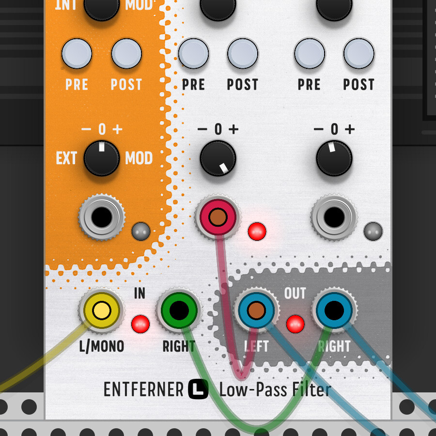
Rerouting the filter output back into the IN or any CV port can create some charming and maybe unexpected effects.
Red cable = modulates (in this case) the Drive
Green cable = add some Resonance and use the OUT port signal to feed it back into the IN port
Version History
Version 2.0.6 (2021-12-10)
- Improved lights when the module is bypassed
- Fixed: DRM issues when used in plugin mode
Version 2.0.5 (2021-12-04)
- Rack 2.0 compatible version
- Supports “Bypass”
- Supports “Light bloom” settings
- Optimized graphics performance (GPU usage)
Version 1.0.4 (2021-07-05)
- Entferner L/H/B: fixed; some parameter changes caused an issue in the stereo signal
Version 1.0.3 (2020-07-07)
- Entferner L/H/B: fixed; modulation could have caused a 0.0Hz cutoff frequency
- added link to the online manual in the popup menu
Version 1.0.2 (2020-06-26)
- Entferner L/H/B: performance improvements
- Entferner L/H/B: optimized self-oscillation handling
Version 1.0.1 (2020-06-25)
- Initial release
Copyright
Oxidlab holds the copyright for the product concept, algorithm, and support material (e.g., manual).
Visual Concept and Artwork: Chris Corrado
